Ohm's Lab
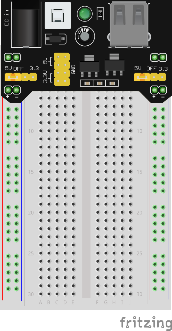
Circuit Lab 0: Breadboard Setup
- Plug the power supply into the top cluster of 5 sockets of the power rail.
- Move the selectable jumper to be in the 5V/VCC position on both the right and left sides.
- Plug the wall adapter into the power supply. Click in the white switch and make sure the LED on the power supply glows.
- Click it off to turn the power supply off.
Circuit Lab 1: Blinky
- Build the circuit below to turn on an LED.
- Use power supply to supply 5V.
- Use a 220 or 330 Ohm resistor and an LED of your choosing.
.PNG)
Circuit Lab 2: Ambient Light
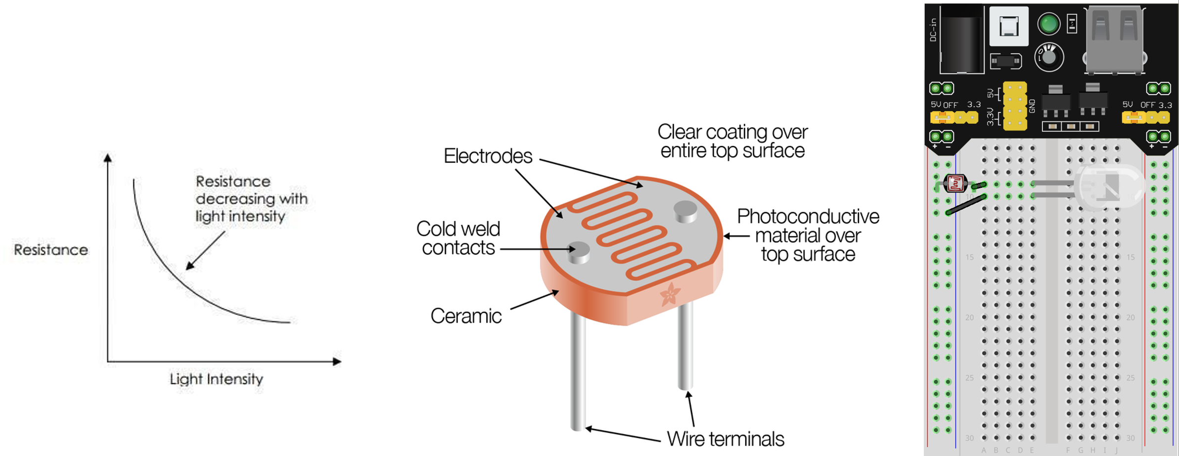
- A photoresistor (also called a photocell) is a type of variable resistor that changes its resistance based on the light intensity.
- Can you use a photoresistor to control the brightness of an LED based on ambient light? (brighter LED when it’s brighter out, like your phone)
- Construct the circuit below by swapping the resistor from the previous lab for a photoresistor.
- Test it with light sources or try to block out the light.
Circuit Lab 3: Heat Indicator
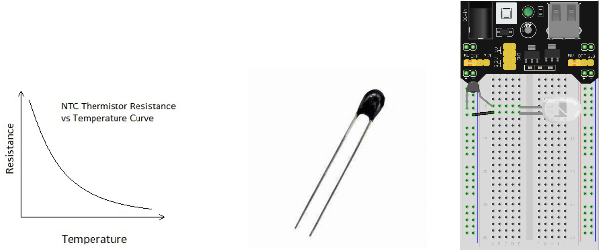
- A thermistor is a type of variable resistor that changes its resistance based on the temperature.
- Can you use an NTC thermistor to control the brightness of an LED based on temperature? Use it as a heat indicator.
- Construct the circuit below by swapping the photoresistor from the previous lab for a thermistor.
- Test it with various heat sources.
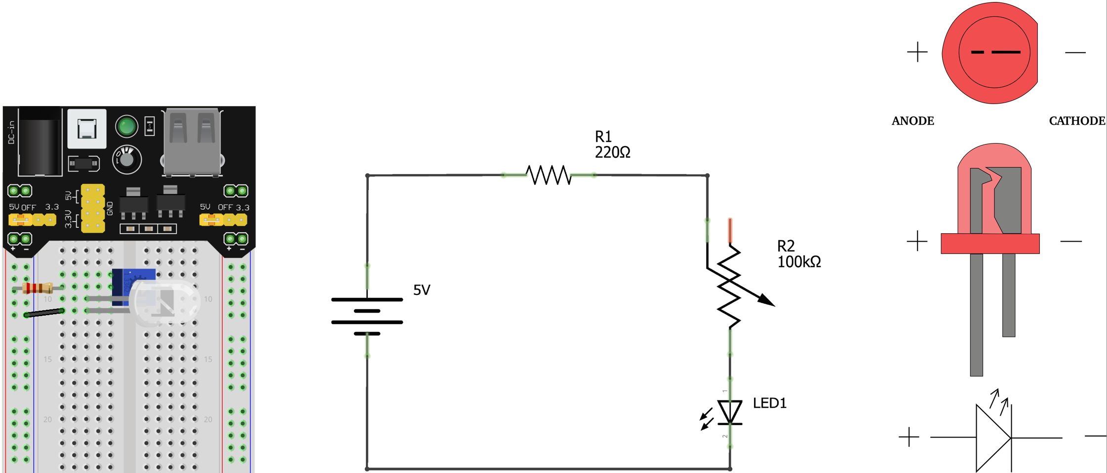
Circuit Lab 4: Dimmer Switch
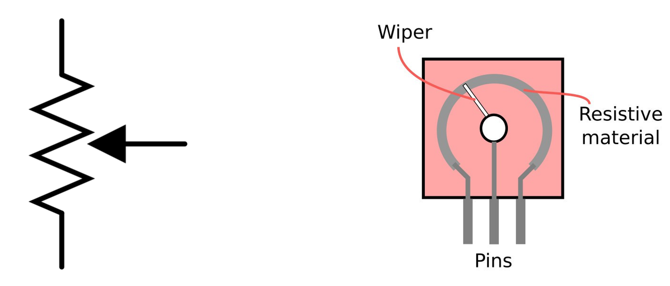
Introducing... Potentiometers!
A potentiometer is a 3-terminal adjustable resistor. Between two end terminals, there is a constant resistance. The middle terminal is called a wiper. It changes resistance value across resistance range as wiper moves.
Instructions
- Use potentiometer as a dimmer for an LED.
- Add 220 Ohm Resistor.
- Use 5V power supply.
- Adjust potentiometer and see how it impacts the LED.
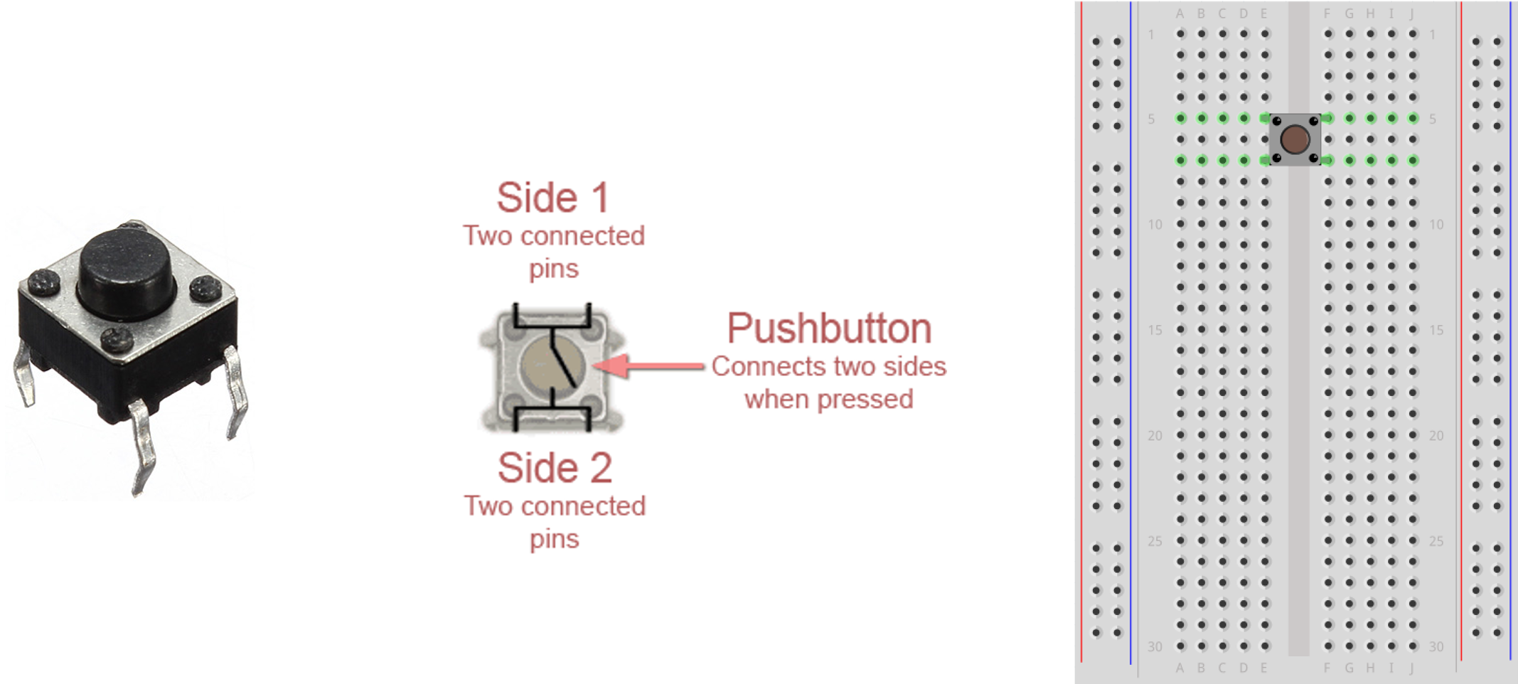
Circuit Lab 5: Switching it Up!
Introducing... Pushbuttons!
A pushbutton (also known as a momentary or tactile switch) is used to switch circuits on and off. It has 4 pins. The pair on the top are connected together internally and the pair on the bottom are connected together internally. All pins become connected together when the button is pressed. Manufactured to plug perfectly across the center gap on a breadboard.
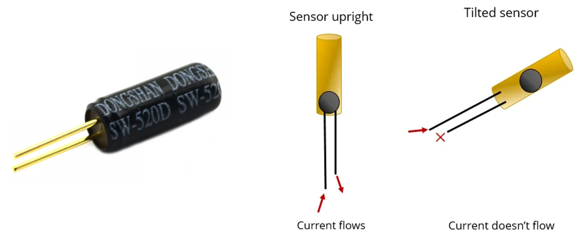
Introducing... Tilt Ball Switches!
A tilt ball switch is a very rudimentary way to tell a circuit's orientation. It has two pins and is switched by tilting the component. In the upright position, the ball rests at the bottom, making contact with the pins. In the tilted position, the ball rolls upwards, breaking the flow of electricity from one pin to the other.
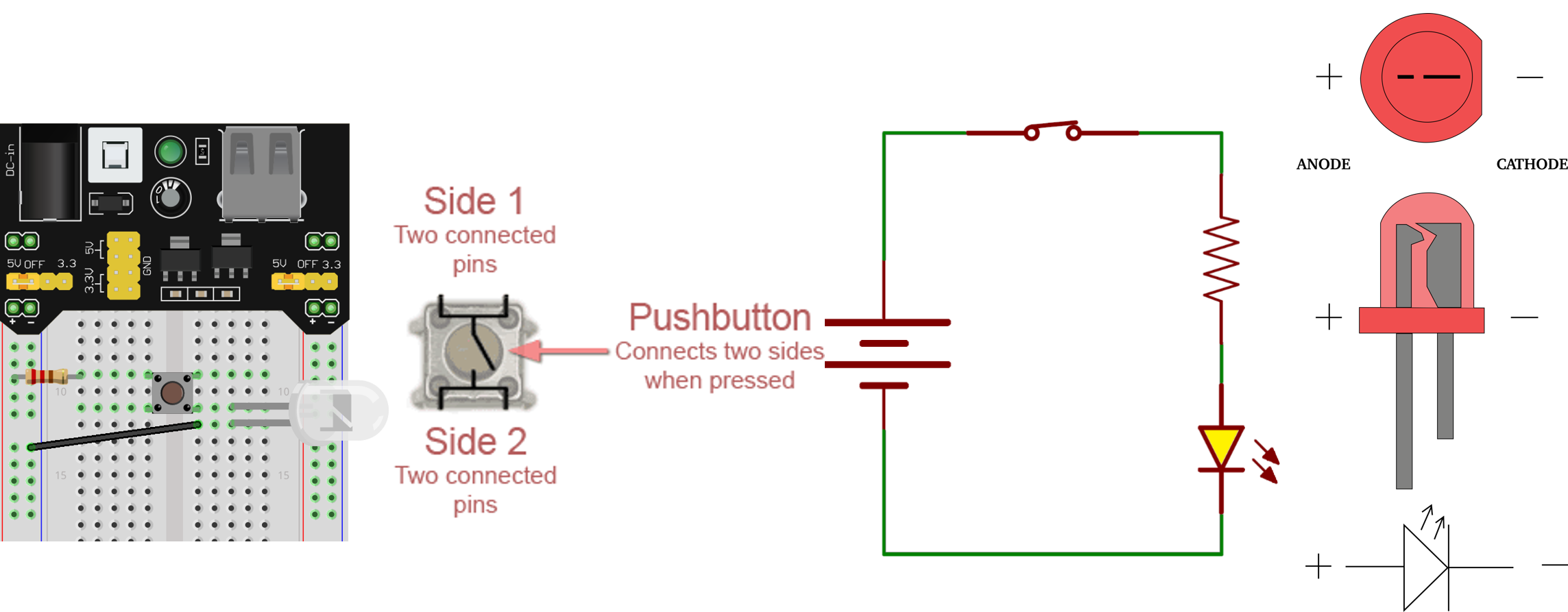
Instructions
- Construct the circuit shown below.
- Use 5V supply voltage.
- Use LED of your choice.
- Use 220 Ohm resistor
- Use a pushbutton switch.
Circuit Lab 6: Color Mixing
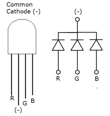
Introducing... RGB LEDs
A single RGB LED is composed of three LEDs inside: a red LED, a green LED, and a blue LED. Common Cathode means that the cathode (negative) end of the individual LEDs are tied together.
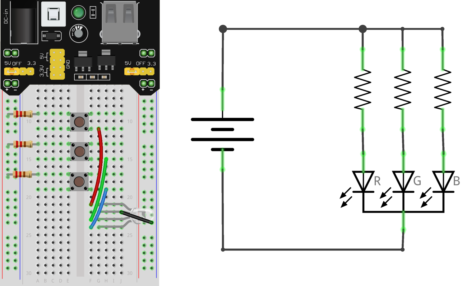
Instructions
- Build a circuit to switch on RGB LED
- 5V Power supply
- 1x RGB LED
- 3x Pushbuttons (1 for each color of the RGB LED)
- 3x Resistors (1 for each color of the RGB LED)
Circuit Lab 7: DIY Circuit
Design a circuit of your own using the components we’ve learned about so far (resistors, photoresistors, thermistors, potentiometers, LEDs, RGB LEDs, switches, etc).