Extension Electronics Lab: 555 Timer Instruments
Integrated Circuits
- A set of electronic circuits embedded into one small chip of semiconductor material.
- Instead of having many discrete components, an IC provides the same functionality in a single package.
- Chips used for many different purposes:
- Amplifiers
- Voltage regulators
- Memory
- Logic gates
- Processors
- Microcontrollers – like ARDUINO!
555 Timer Background Info
Serial/Parallel Capacitances
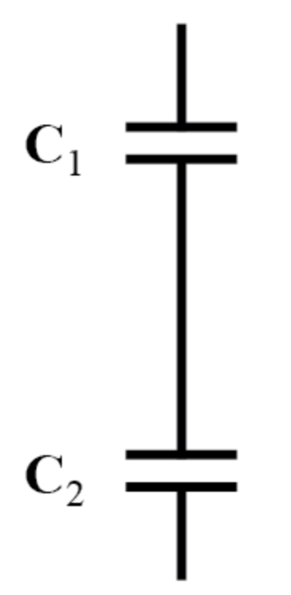
- Series Capacitors - combines similarly to parallel resistors -
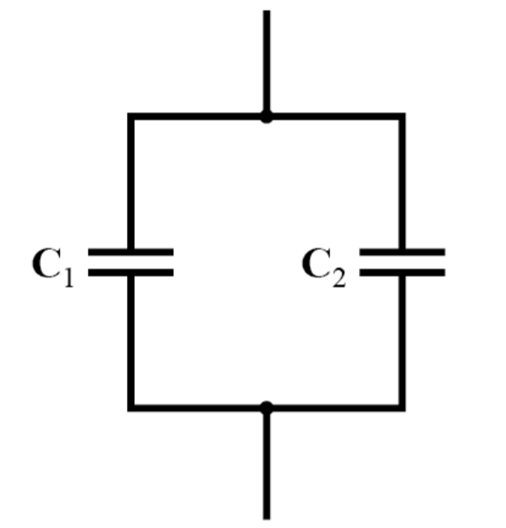
- Parallel Capacitors - Same as series resistors -
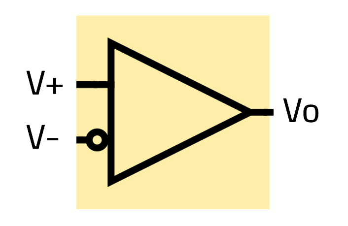
Comparator
- A device that compares two voltages and outputs a digital signal indicating which is larger. It has two analog input terminals V+ and V-, and one binary digital output Vo.
- Vo = 1; if V+ > V-
- Vo = 0; if V+ < V-
S-R Flip Flop
- A "latch" circuit is used to store information. It has two stable states.
- S – Set, drives output Q high
- R – Reset, drives output Q low
- R1 - Resets the latch.
555 Timer
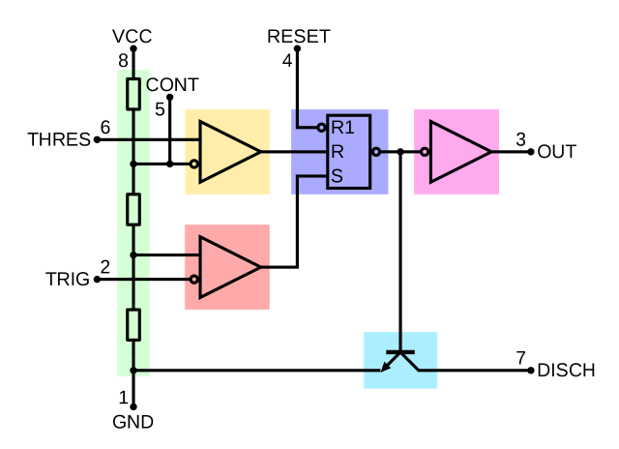
- Green: Between the positive supply voltage VCC and the ground GND is a voltage divider consisting of three identical resistors, which create two reference voltages at 1/3 VCC and 2/3 VCC. The latter is connected to the "Control Voltage" pin. All three resistors are 5 kΩ.
- Yellow: The comparator negative input is connected to higher-reference voltage divider of 2/3 VCC (and "Control" pin), and comparator positive input is connected to the "Threshold" pin.
- Red: The comparator positive input is connected to the lower-reference voltage divider of 1/3 VCC, and comparator negative input is connected to the "Trigger" pin.
- Purple: An SR flip-flop stores the state of the timer and is controlled by the two comparators. The "Reset" pin overrides the other two inputs, thus the flip-flop (and therefore the entire timer) can be reset at any time.
- Pink: The output of the flip-flop is followed by an output stage with push-pull (P.P.) output drivers that can load the "Output" pin with up to 200 mA (varies by device).
- Cyan: Also, the output of the flip-flop turns on a transistor that connects the "Discharge" pin to ground.
555 timer square wave simulation - http://www.falstad.com/circuit/e-555square.html
555 timer internals simulation - http://www.falstad.com/circuit/e-555int.html
555 Timer Operating Modes
- Astable (free-running) mode – the 555 can operate as an electronic oscillator. Uses include LED and lamp flashers, pulse generation, logic clocks, tone generation, security alarms, pulse position modulation and so on.
- Monostable mode – in this mode, the 555 functions as a "one-shot" pulse generator. Applications include timers, missing pulse detection, bounce-free switches, touch switches, frequency divider, capacitance measurement, pulse-width modulation (PWM), and so on.
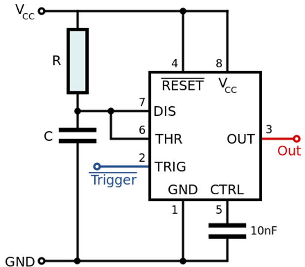
Astable Mode
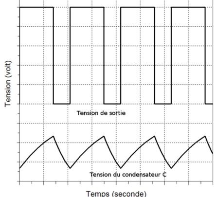
- Puts out a continuous stream of rectangular pulses having a specific frequency determined by R1, R2, C.
- Output high when trigger less than 1/3 Vcc, low when threshold greater than 2/3 Vcc.
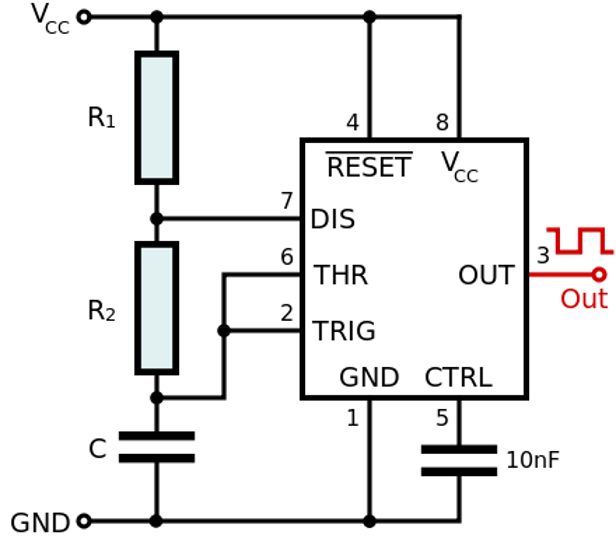
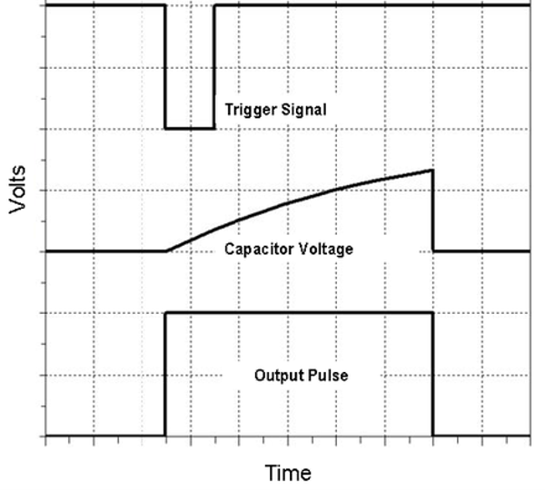
Monostable Mode
- Similar to astable but requires external trigger (driven by another source).
- Output driven high when trigger drops below 1/3 Vcc, and driven low when the threshold charges to 2/3 Vcc.
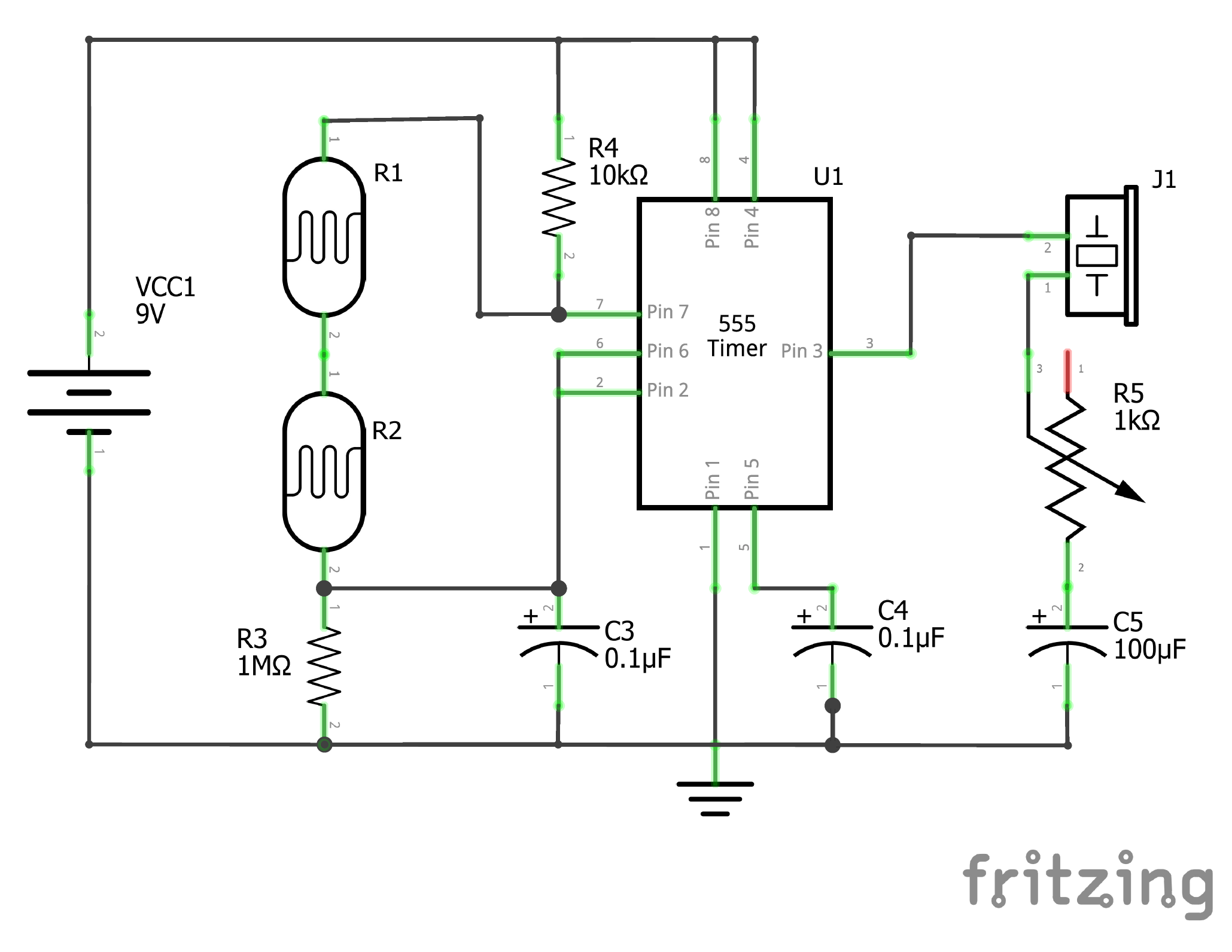
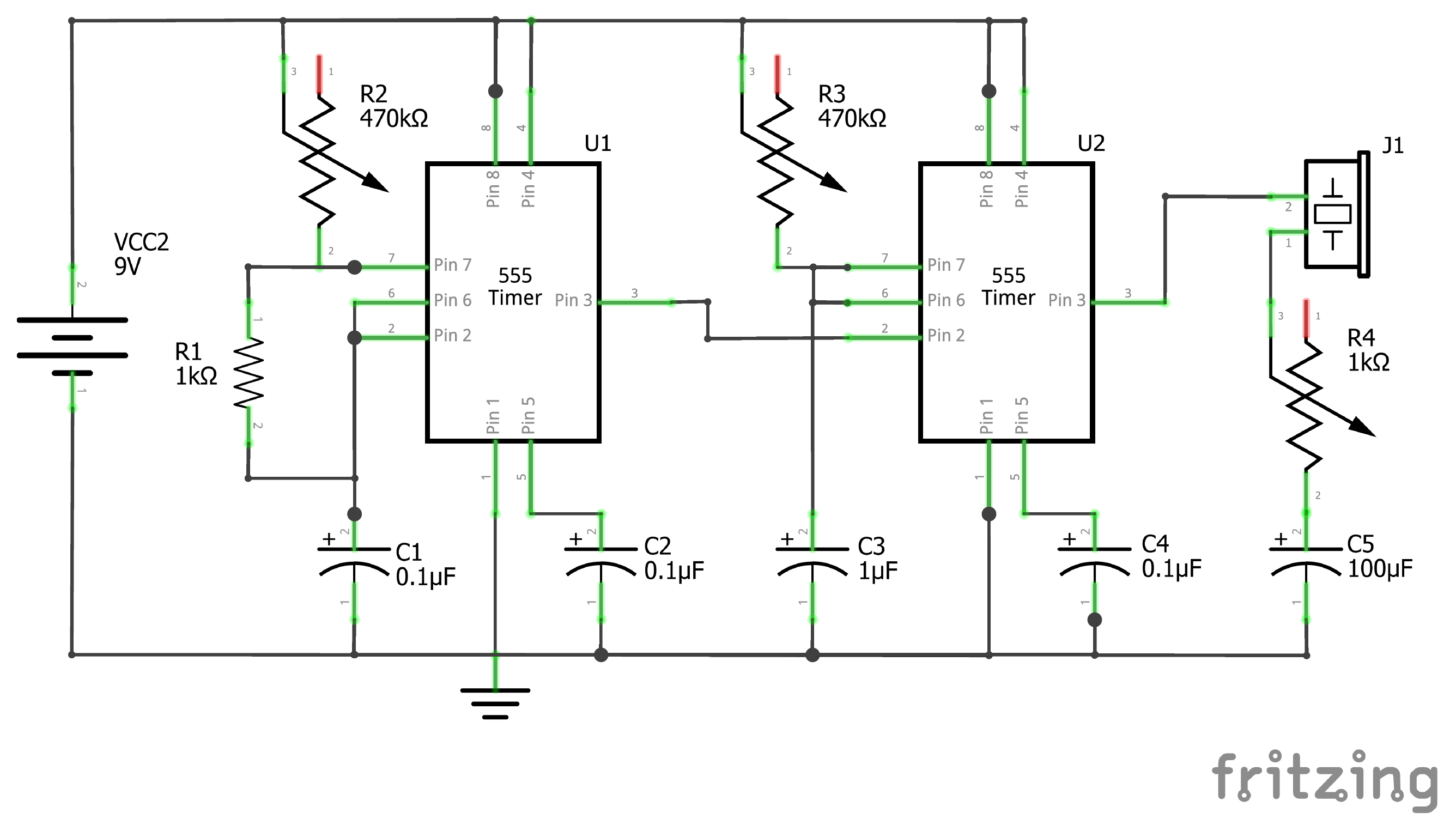
555 Timer Instruments
Full Tutorial: https://www.instructables.com/Battle-of-the-Bands-555-Timer-Edition/
Demo:
Theremin
Atari Punk Console
Organ